

Building a plotter (part 2)
So the Makerbase MKS DLC32 arrived. My challenge was how to mount it onto the frame and keep all the wires hidden.
Normally I would fire up OpenSCAD and get my calipers out and risk the wrath of my family while I disappear for 3 days designing the enclosure to print.
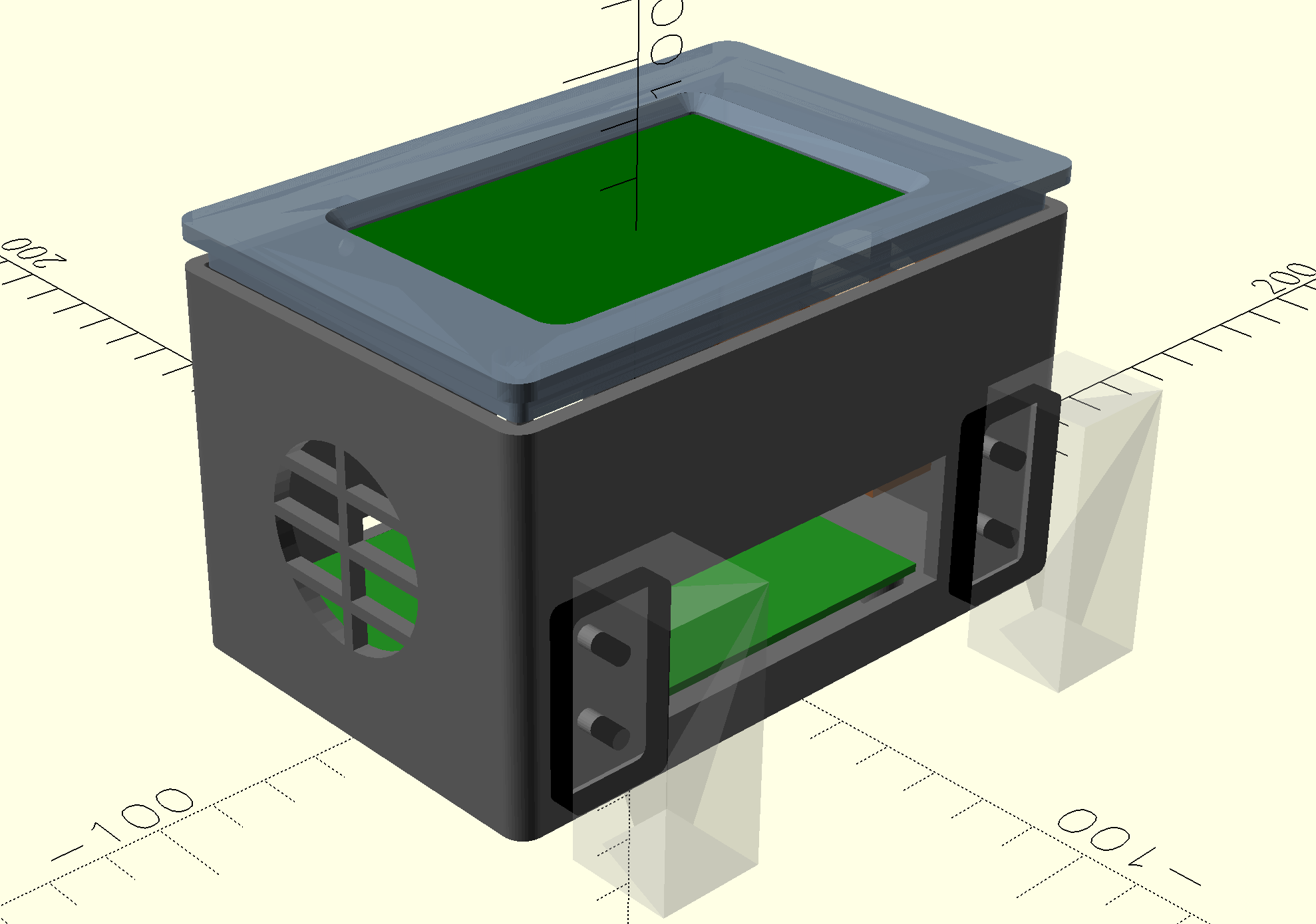
This time I said, let’s see what the LLMs can do.
So I loaded up a directory with:
- The Makerbase user guide (which includes sizing diagrams)
- The Draw bot assembly instructions
- Some photos of the join point with a ruler included.
I then asked Codex to design the enclosure…
The first design was ugly… sadly I didn’t save it. The main issue was that it didn’t think to put the display above the PCB. Instead there was one half of the box just for the display (with empty box underneath) and the other half of the box for the PCB (with empty box above).
So one steer later and we had a reasonable design… just with lots of holes… but it was perfectly functional.
Spoiler: For Part 3 I had given Codex a camera so it can see.
I told Codex there was something wrong with the design, but didn’t say what specifically, so it took a picture and immediately diagnosed the issue.
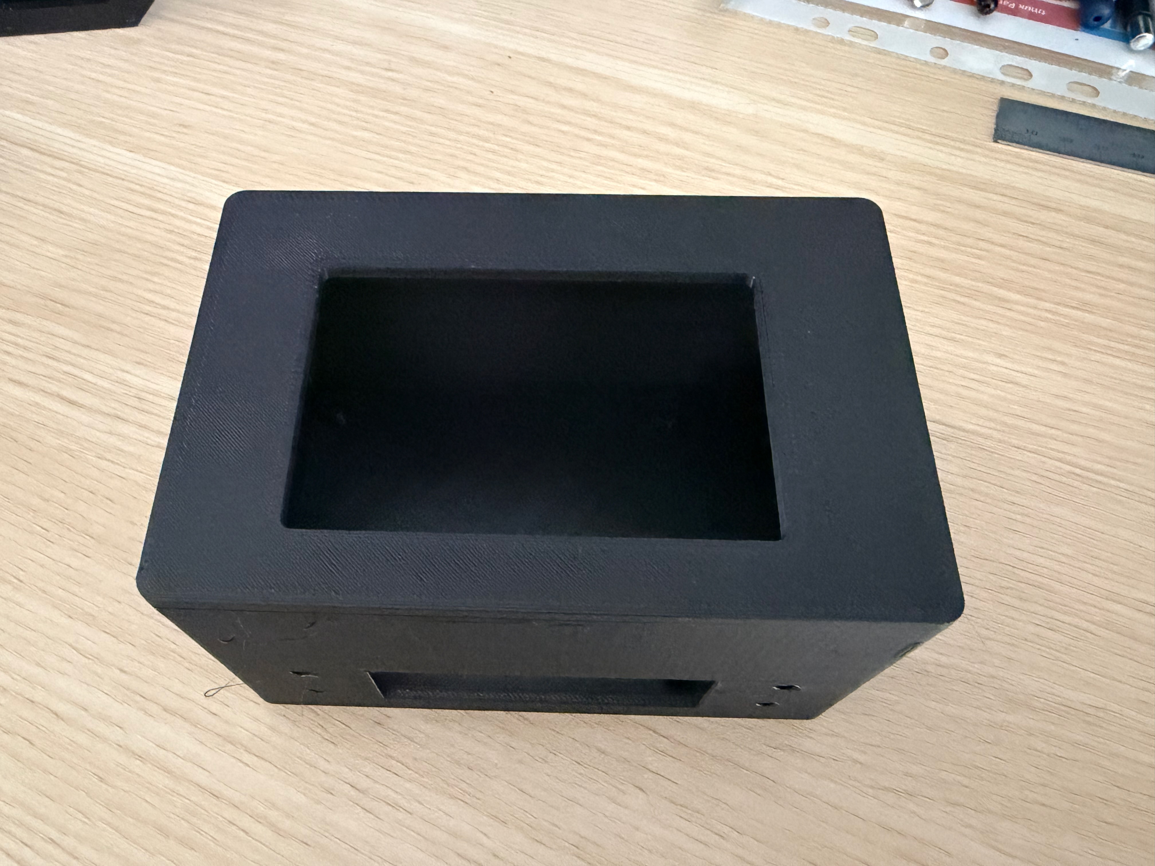
Here’s What the first version looks like:
Here’s the photo Codex took:
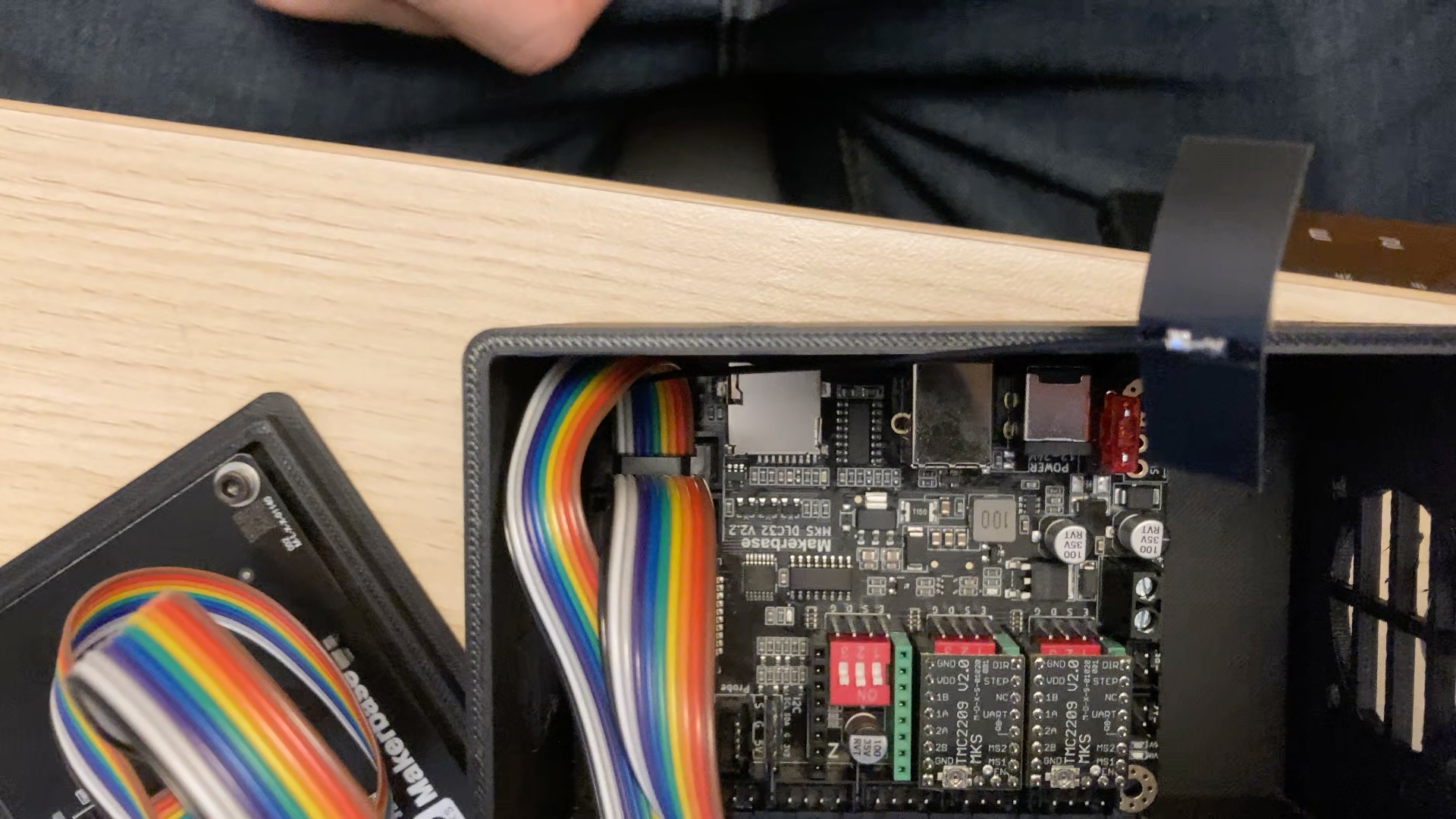
Can you see what is wrong?
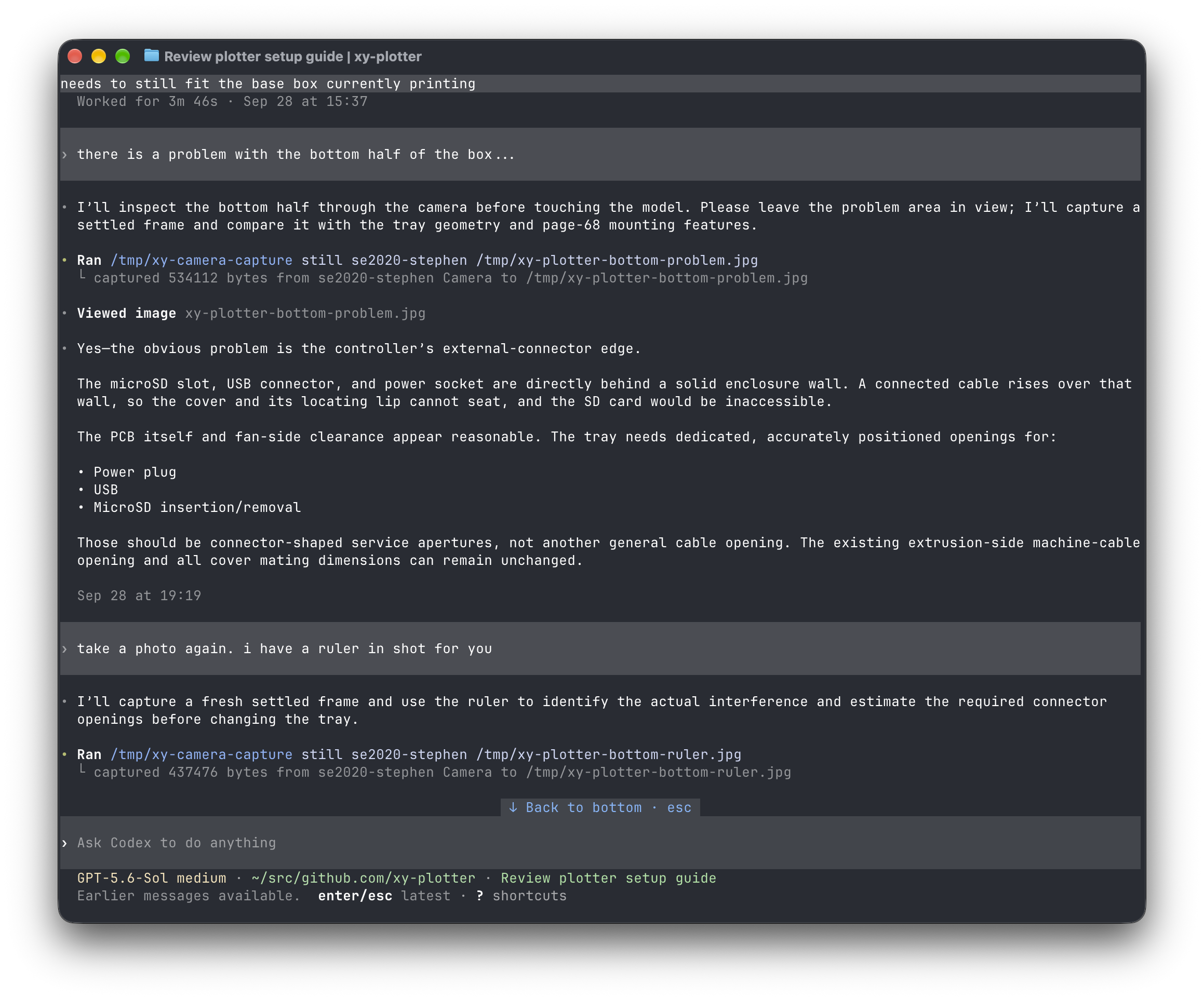
After some redirects to bevel the display mount and confusion on which side to add the missing holes on, both of which I caught in the 3D viewer, we got this mostly fine print…
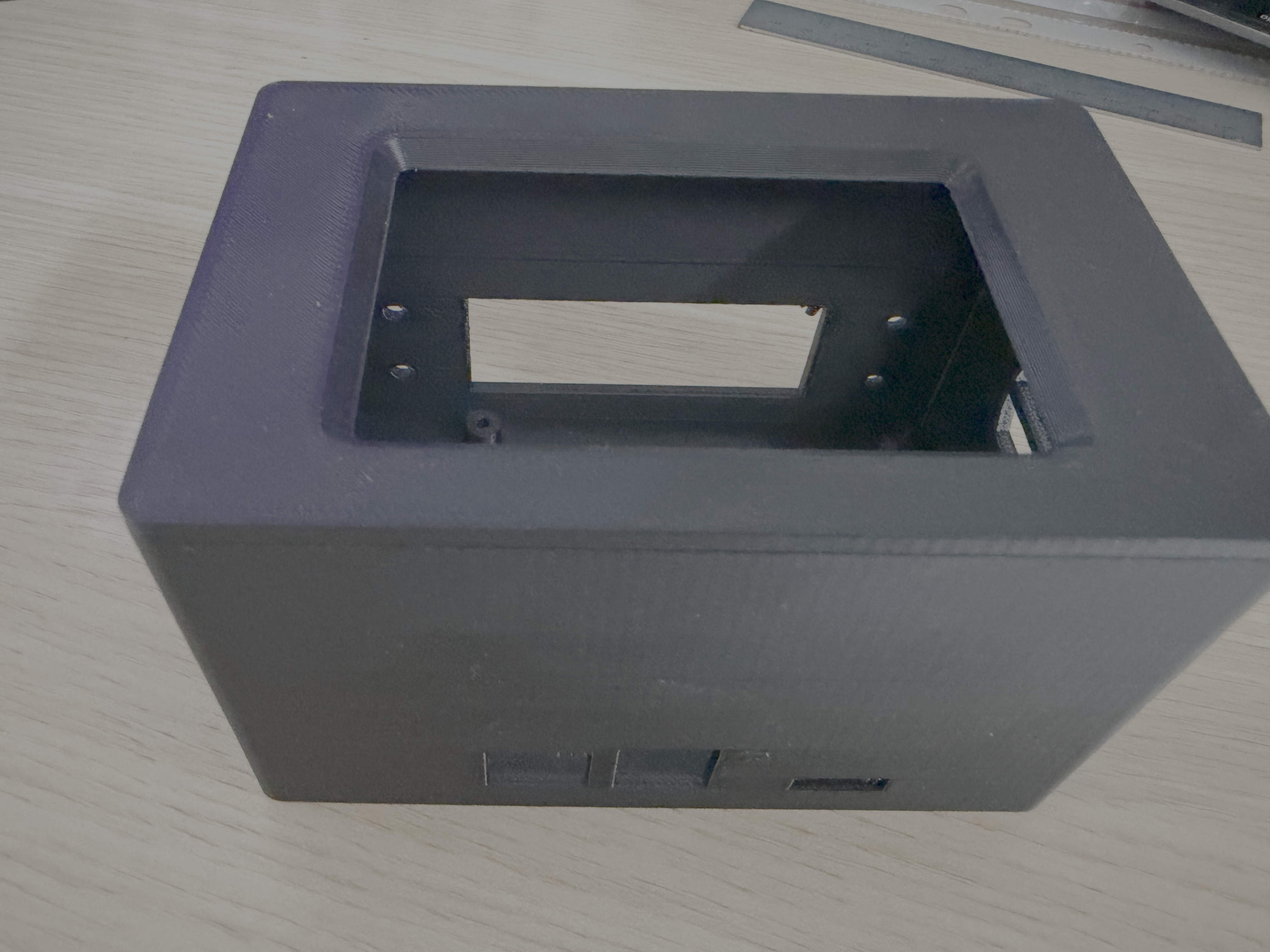
I say mostly fine as some of the offsets were wrong and needed tweaking…
So now we end up at the third and final print
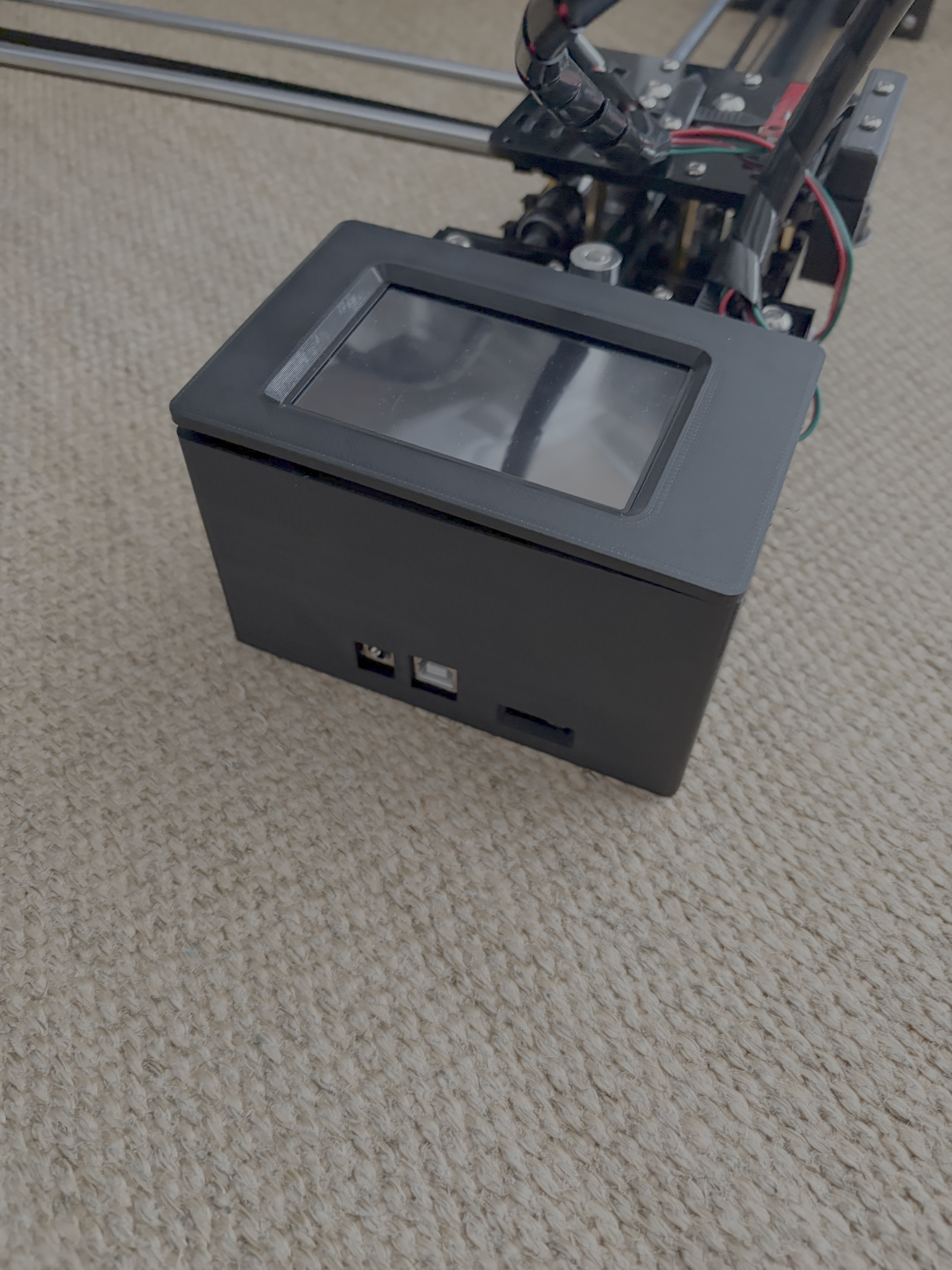
All in all I am really happy with this print.
Part 3 will be all about getting the touch screen working and configuring the plotter to actually work!